Monday, January 31, 2011

PIC MIDI expander with old ISA-BUS Soundcard

PIC project - MIDI expander
The circuit makes possible to realize a small MIDI expander using an old ISA-BUS soundcard. This microcontroller project based on micro PIC18F4320. Emilio, project designer, has tested on 2 different cards, and it should work for any card ADLIB OPL3 compatible (the I/O address MUST be 0x388).

The software responds to MIDI commands on Channel 1. The sounds are generated by the FM synthesizer built in the soundcard. The power is derived from two low-cost wall transformers (see picture) with variable output, set to 9V (the output is close to 12V).

Download :
Source code and schematic

search term : Midi expander, ISA BUS, Microcontroller PIC project (src)

Infrared Thermometer Module

Electronic Infrared Thermometer Module
If you want to build non Contact Thermometer, you can try to use MLX90614. It will reduce your electronic project complexity. Outputs of this module is continuous data flow with an active alarm running in the background, 16-bit digital temperature output data that ranging from -70 °C to 380 °C and Serial data (Auto-baud detection (2400, 4800, 9600, 19.2K, 38.4K)) for microcontroller-to-MLX90614 communications.

tags: Electonic Module, Infrared Thermometer (src)

Electronic Project : AVR Lux Meter

Electronic Project : AVR Lux Meter
The illumination is how the level of flows of light falling on a surface. The flow of light is visible, which is defined in the flow (the light power) divided by relative sensitivity of the naked eye on the visible spectrum. This means that the Lux is well suited to the light level of meaning to the human eye. To measure the lighting, we can use Lux Meter.
We can build ourselves Lux meter using electronic components. At the detection of light we use photo diode. However, there is a difference between the spectra simple answer photo diode silicon and the naked eye, it can not be used for lux meter. Some photo diodes for lighting have a sensor compensation color filter on the window to correct its response spectra.
In this project, Photo-diode current results light that is well proportional to the light input power when used in short fashion. In this lux meters, the output current is converted into a voltage converter with an IV, he is caught by a micrcontroller AVR and displayed in terms of lux. The ppamp U1 in the circuit diagram that acts IV conversion circuit and its conversion becomes 50mV / μ A, in accordance with a record of comments R5. The capacitor C5 is to obtain the correction, it cancels Ct of the photo diode (about 200 pF). In this case, greater capacity in May rather be 220 pF because the high frequency signal is not necessary. The lux meter is powered by a 9V battery.

Download schematic, document, firmware (zip) here
[source]

Sunday, January 30, 2011

USB Audio Digital to Analog Converter

USB Audio Digital to Analog Converter
I want to build high quality preamplifier with built-in DAC from SPDIF or USB for my power amplifier Leachamp. I tried to design DAC from USB with this circuit on one-sided PCB and I was successful.

Schematics is from datasheet of PCM2902. Circuit includes DAC and ADC, SPDIF output and input and HID part with 3 buttons for MUTE, VOL+ and VOL-. I used only DAC part. Other parts are not used. For high quality playback is needed to use external low-drop voltage stabiliser for DAC part. I used LP2951CM which was available at local store. Output voltage is set to about 3.7V with two resistors. Circuit board is designed regarding to good ground placement and separating of analog and digital ground. These ground are connected in one point at USB connector.

[source]

Hummer RC Truck, AT90S8535

Hummer RC Truck
For our final project, we decided to enhance the controls of a Hummer RC truck. Our main objective was to demonstrate that an Atmel microcontroller together with basic hardware building blocks can replace all of the car’s original circuitry. Improving the RC truck’s handling involved adding analog control over steering and speed.

The original construction of the car hindered this idea and forced us to resort to some mechanical engineering (mounting a servo) to resolve the problem! Overall, the project was a great deal of fun and involved a lot of tinkering with hardware (including dangerous flirtations with nearly exploding power transistors!)

Link : Hummer RC Truck, AT90S8535

GPIB to USB converter Using PIC

GPIB to USB converter Using PIC
PIC-plot now goes to USB! A perfect low cost solution to quickly get screen plots of your GPIB instrument on your laptop PC without complex software. It emulates the HP7470A operation on the GPIB side, and outputs the HP-GL data at the USB port to be read and stored on the PC by any capturing software. GPIB addresses and other set-and-forget parameters can be configured by a simple Setup menu, then no Dip-switches are used. Power is taken from the USB port to simplify cabling and get rid of a DC adaptor.

The operation of this interface is not just limited to digital plotter emulation: any data intended to be received by a GPIB Device (addressable or listener only) can be captured from the instrument and brought out to the USB port, including raw measurement arrays or rasterized data for a graphic printer. It is based on a PIC16F628 microcontroller and an FT232R chip. PCB size is just 57x64mm.

[source]

Saturday, January 29, 2011

LED Fader Project

Microcontroller - LED Fader Project
If you like make a LED project? LED Fader 2 could be interesting electronic project to build up. LED Fader 2 is a program that can control up to 16 outputs for driving LED's. All 16 outputs are pulse width modulated, giving 256 levels of brightness at a refresh rate of 100 Hz. A script language, designed for controlling the outputs, is provided as well. The program is written in AVR assembler for the AT Mega8 and Mega16 microcontrollers.


Download :
Source Code and Documentation

tag : LED, AVR Microcontroller Project (src)

The Ethernet Shield For Arduino

Arduino project Ethernet Shield For Arduino
Here is an ethernet shield for Arduino. This module gives Arduino the ability to open connections to other Internet hosts or behave like a server, for example a simple web server. The design uses the w5100 chip from WizNet that implements the whole IP stack in itself providing up to 4 sockets simultaneously.

Download : Documentation and guide
related search : Arduino project, ethernet shield, electroonic project (src)

Microcontroller based Photoplotter

Microcontroller Project - Photoplotter
A photoplotter is a printing device that exposes light to a photo sensitive film to produce output. The film is then developed like traditional photos to get the result. There are 2 types of photoplotter, vector type and raster type. Vector plotters move the exposure light anywhere in 2D space to create the image. Need a line from point A to B? No problem, just move from A to B. These are similar to old style pen plotters. Raster plotters, are more like a dot matrix printer, sending out one line of dots, then moving to the next to create an image.

related search :
Elelctronic circuit, Photo plotter, Microcontroller project (src)

Wednesday, January 26, 2011

Microcontroller based Photoplotter

A photoplotter is a printing device that exposes light to a photo sensitive film to produce output. The film is then developed like traditional photos to get the result. There are 2 types of photoplotter, vector type and raster type. Vector plotters move the exposure light anywhere in 2D space to create the image. Need a line from point A to B? No problem, just move from A to B. These are similar to old style pen plotters. Raster plotters, are more like a dot matrix printer, sending out one line of dots, then moving to the next to create an image.

related search :
Elelctronic circuit, Photo plotter, Microcontroller project (src)

Burning the Bootloader without external AVR-Writer

Burning the Bootloader without external AVR-Writer
When we burn the bootloader of Arduino Diecimila, we connected external AVR-Writer to ICSP of Diecimila. But Kimio found the method to burn the bootloader by Diecimila itself without external AVR-writer. It is able to do by FT232RL BitBang Mode AVR-Writer software. And, this method is usable in Arduino NG and Arduino Duemilanove too.

tags : Arduino Diecimila, AVR, Digital Electronic (src)

MAX3420 - USB Peripheral Controller

MAX3420 - USB Peripheral Controller
The MAX3420 provides a very simple approach to adding a USB interface to a circuit. It uses a SPI bus to connect to your system. It does require a reasonable amount of configuration and control, so you'll need to connect it to some form of microprocessor/microcontroller.

Download : PCB and Circuit in Eagle

related search : Digital Electronic Project, USB Controller (src)

Tuesday, January 25, 2011

RF remote control using microcontroller AVR


Using remote control make our work more easier. like turn off Air conditioner, change channel TV, play your home theater and more. There are many type of remote control like Infrared, Radio Frequency, SMS and more. To control device behind the wall like garage door you can only use Radio Frequency remote control. Because the other can not bypass the wall.

Here is RF Remote control using microcontroller created by serasidis. There are two part in this electronic project : transmitter and receiver. The transmitter is constituted by AT90S2323 microcontroller and TLP434 RF transmitter module at 418MHz. the transmitter designed for battery economy use and safe transmition of the data. The receiver constituted by RF receiver module RLP434A at 418MHz, the microcontroller AT90S2313 and the 2 relays with can handle any electric (or electronic) device up to 10 Amps (the contacts of my relays are 10Amp at 250Volts).For antenna you can use a cable 30 - 35cm long.

Download here for documentation, firmware, source code and schematic.
[link]

RF and IR Remote Control

PIC remote control IR and RF
This PIC based remote control allow you to control up to 8 devices by this easy constructable remote control. The project very flexible you can use it as radio remote control or infrared remote control, depending on the components. Each device output can be configured to be momentary (turned on while you press the button) or latched. Latched outputs can be toggled on/off by one button per channel, or turned on and off by two buttons per channel.

tag : IR remote control, RF remote control, wireless project control
[link]

PS to USB Joystick Converter

PS to USB Joystick Converter
If you have PS 1 or PS 2 joystick and you want use it for USB. Well this microcontroller project could resolve your problem now. PS2USB converts two Playstation 1 or Playstation 2 converter into usb josysticks. It also features the Dance Pad Code (Up+START+SELECT), so that it can be used in DDR games (tested with Stepmania). Works under Linux, Mac OSX, Windows.
note : no picture for the project, i just replace it with analog PS 1 joystick
Download :
source code and schematic

search term : PS to USB, Converter, Microcontroller Project (src)

Monday, January 24, 2011

AVR XMEGA


ATMEL Launching new microcontroller AVR Family : AVR XMEGA

"The new AVR XMEGA™ family from Atmel brings 8/16-bit microcontrollers up to a new level of system performance. Increased focus on system performance is important because more and more 8/16-bit microcontroller families do not meet today’s requirements. Requirements for higher embedded performance combined with reduced cost, size and power consumption mandate new microcontrollers designed especially to combine and offer all these requirements in the best possible way. With AVR XMEGA Atmel is the reference for 8/16-bit microcontrollers."

AVR XMEGA devices include:
  • 2nd generation of picoPower technology
  • Innovative Event System for fast, CPU independent inter-peripheral communication
  • 4-channel DMA Controller boosts MCU performance
  • 100% predictable timing
  • Fast 12-bit ADC and DAC
  • Fast Cryptography support for AES and DES
For detail click here

Electronic Tools : Weller WLC100 Soldering Station

Weller WLC100 Soldering Station
Soldering Iron is a must have tool for electronic engineer or Hobbyist. Choosing good soldering iron can make your electronic project designing process faster and have good result in circuit connection.

The Weller WLC100 Soldering Station includes everything you need to start using solder to join metals and create efficient, electrical connections. Designed with the hobbyist and the do-it-yourself enthusiast in mind, this kit features a high-quality, lightweight pencil iron with variable power control, a cushioned foam grip with a replaceable heating element, and a safety guard iron holder. And it’s from Weller, the world leader in soldering since 1945.

MC9S08GT60 Virtual Interactive Boxing

Microcontroller Project - Virtual Interactive Boxing
The creative Virtual Interactive Boxing system makes shadow boxing more interesting by providing a virtual opponent with whom to spar. Designed around an MC9S08GT60 microcontroller and an MC13192 RF transmitter, the system monitors the user’s performance. Enhancements include digitized audio and speech that provide motivational cues and feedback about the user’s performance to help him improve his technique.

Download :
Download Project | View Abstract

Tags : MC9S08GT60 microcontroller, MC13192 RF transmitter, Microcontroller Project

Sunday, January 23, 2011

LCD2USB : Connect LCD to PC via USB

LCD2USB : Connect LCD to PC via USB
LCD2USB is a open source/open hardware project created by Till Harbaum. The goal of LCD2USB is to connect HD44780 based text LCD displays to various PCs via USB. LCD2USB was meant to be cheap and to be made of easily available parts. It is therefore based on the Atmel AVR Mega8 CPU and does not require any difficult to obtain parts like separate USB controllers and the like. The total cost (without display and pcb) are about 5 to 10 Euros. LCD2USB currently comes with a simple demo application that works under Linux, MacOS X and Windows.

Download : Schematic, Souce Code

tags : LCD, USB, AVR, Microcontroller, Interfacing (src)

New AVR Microcontroller for Smart Card Reader Applications

AVR Microcontroller for Smart Card Reader
Atmel introduce its new AVR microcontroller designed for smart card reader applications. Based on the AVR 8-/16-bit RISC core allowing single cycle instruction execution, the AT90SCR100 embeds 4 Kbytes of EEPROM for data, 4 Kbytes of SRAM and 64 Kbytes of programmable FLASH providing all the flexibility required for fast software upgrade and customization reducing significantly time to market and development costs both during development phase and product life.

The AT90SCR100 offers a comprehensive set of interfaces such as ISO7816 (Class A,B,C supported), USB full Speed 2.0 device and host, USART and TWI to address any applications that interface to synchronous, asynchronous and USB smart cards. In addition, a SPI serial interface plus a dedicated High Speed SPI interface (up to 20Mbps at 20MHz) have been implemented. Respectively combined with an RF front end and/or with a fingerprint sensor, the AT90SCR100 is ideally suited to contactless and/or Biometric reader applications. With its 38 GPIOs in its high pin count configuration (64 pin package), it can also address all USB Keyboards integrating the smart card reader functionality.

Availability and Pricing
Samples for the AT90SCR100 are available now. Packages are available in 32-pin QFN, 64-pin QFN and 64-pin QFP. Volume production will start in May 2009. Prices start at US$ 3.00 for the 64 pin count version and at US$ 1.90 for the 32 pin package in 10,000 quantities.

related search : news, atmel, microcontroller, smart card reader, avr (src)

Card Reader using Microcontroller

Card Reader using Microcontroller
This is a simple version of Card Reader. Why? because this Magnetic Card Reader only in read only environment. It only read the information stored in magnetic card. The purpose of the project is used as card debugger. There are three main part in this project :
  • A reader to capture digital characters from the card
  • A RISC microcontroller to store data and check for errors
  • A display to relay the magstripe contents to the viewer
As processor it use microcontroller AVR ATtiny 2313. For Reader it uses Panasonic ZU-M2121S451 Reader. and for display use LCD 16x2.
The Magstripe (Track 2) Reader project can be used to view numerics stored a magnetic data card. Although there is no writeback ability, the device is very useful as a card debugger. The treatise will use an LCD character display to relay this data to the user. The circuit uses an AVR microcontroller and can modified to work with similar RISC controllers.
Although the card reader can't write back to magnetic card, I guess this is a one of good reference to learn how card reader work. For download the reference clik here (zip file)or visit this link
Thanks to Brady Mayes for great card reader based on microcontroller.

Saturday, January 22, 2011

Project : Radio Controlled Clock with USB

Electronic Project - Radio Controlled Clock with USB
Most widely spread DCF77 radio-controlled clock receiver are connected computer via the serial port but this electronic project will show you how to make DCF77 radio clock receiver connected via USB using a small 8-pin microcontroller ATtiny45. The project programed with the smart firmware called AVRUSB and AVR-CDC. With this firmware combination, the DCF77 receiver creates a serial port and is fully compatible to old-style true-serial-port ones. No software adaption is necessary.

Download : schematic and Firmwire

tags : Microcontroller AVR Project, radio-controlled clock receiver, USB (src)

Arduino Duemilanove Project Board

Arduino Duemilanove Project Board
The Arduino Duemilanove ("2009") is a microcontroller board based on the ATmega168 (datasheet). It has 14 digital input/output pins (of which 6 can be used as PWM outputs), 6 analog inputs, a 16 MHz crystal oscillator, a USB connection, a power jack, an ICSP header, and a reset button. It contains everything needed to support the microcontroller; simply connect it to a computer with a USB cable or power it with a AC-to-DC adapter or battery to get started.

Download : Eagle Files (zip) and Schematic (PDF)

related search : Microcontroller Board, Arduino, ATmega168 (src)

LM35 and TL431 Automatic Temperature Control

Electronic Project circuit - Automatic Temperature Control
This is an electronic circuit that can be used as automatic temperature control application. The circuit switches a miniature relay ON or OFF according to the temperature detected by the one-chip temperature sensor LM35. When the LM35 detects a temperature higher than the preset level (set by VR1), the relay is actuated. When the temperature falls below the preset temperature, relay is de-energized. The circuit can be powered by any AC or DC 12V supply or battery (100mA min.)

Download : schematic, layout and PCB (pdf)
related search : Electronic circuit project, automatic application, temperauter controller, LM 35 (src)

Friday, January 21, 2011

Computer Controlled Battery Manager

Computer Controlled Battery Manager
BattMan II is a computer controlled battery manager, intended for typical rechargeable batteries used by R/C and electronics hobbyists, as well as various consumer product batteries.

BattMan II has the following capabilities:
  • Works with Nickel-Cadmium (NiCd), Nickel-Metal-Hydride (NiMH), Lithium-Ion (Li-Ion), Lithium-Polymer (LiPo), Lithium-Nano-Phosphate (LiNP), and Lead-Acid (Pb-Acid) batteries of 1.2 to 14.7 Volts.†
  • Discharges batteries to measure capacity at rates of 130mA to 2A.
  • Charges at rates of 130mA to 1.3A.†
  • Automatically performs repeated discharge/charge cycles to break in new batteries, or erase NiCd voltage depression in old ones.
  • Measures internal resistance.
  • Monitors self-discharge.
  • Real time graphical display lets you see problems like mismatched cells.
  • Keeps a log of all operations performed, which can be imported into any spreadsheet program.
  • Saves graphs of charge, discharge, auto-cycle, and monitor operations.
  • Connects via parallel port to any PC running Microsoft Windows (95, 98, ME, 2000, XP, or Vista).
  • Operating software, complete with source code, is available to download.
Download schematic and software
releated search: Electronic Circuit Project, Battery manager (src)

Controlling LCD using BASCOM and AVR

Controlling LCD using BASCOM and AVR
Bascom can handle the two main types of liquid-crystal displays: alphanumeric and graphic. For the time being we will concern ourselves with the most common alphanumeric type. This type of LCD can display characters, numbers and special characters. The most common type of alphanumeric LCD uses a Hitachi HD44780 as display controller. When you are uncertain about what type of display you are holding in your hands, simply look at the chip designations on the back. If one of these says HD44780 you're safe.

Fortunately, the default is set to LCD type 16*2. This is the most common LCD with two lines and 16 characters per line. HD44780 type LCD's have eight datalines, but they can be controlled in a more economical way by using the four 'upper' lines. This saves four i/o pins on your controller. This is the default (4-bit bus mode) in the options window. Sending data in the 4-bit bus mode of course takes two writes for each 8-bits to send. If you really need the LCD to be as fast as possible (and you seldom do) you will have to choose the 8-bit bus mode.

source : qsl.net

Thursday, January 20, 2011


jaksdak sjh ashdakshdka dshaksdjh aksdna

AVR Frequency Counter

AVR Frequency Counter
Do you need an avr counter that can measure for 40Mhz and low cost for this project? Well take a look at microcontroller project : avr counter created by Murray GreenMan. This microcontroller project also give you some interesting feature like : 8 digit LCD display and there is an optioanal PC telemetry so you can watch the output on a PC.
"The counter contains only three inexpensive ICs (well, add a regulator and three transistors), and operates from 6 - 15V DC at about 25mA. The most expensive single item is the LCD display, which is an industry standard 16 x 2 dot matrix module, which can often be found used or at bargain prices. This isn't a kitset, but the parts are easily obtained, and the circuit can be built using any prototyping technique, or you could design your own PCB. The prototype was built on a small commercial strip board."
[Link]

Logging System & Data Acquisition

Data Acquisition & Logging System Using AT89c51
This microcontroller project log the temperature system. It can be used to monitoring and controlling environment temperature as we needed. i know that the chip, AT89C51, little out of date, but at least we can still learn the system How to make Data Acquisition & Logging System with microcontroller. This great project made by Abbas Raza.

"The status and temperature date saved to PC via serial communication. Here 8 temperature sensors are connected(4 shown in diagram for simplicity). values of all the sensors are sent serially by AT89C51 to pc. Software "DAQ System " takes these values and show them on its front panel, and also logs them to the data base "daq.mdb" .we can set some parameters like set point , low limit ,and high limit . when temperature of some sensor increases beyond set point ,the heater connected to controller (specific for that sensor) will be turned OFF( ON in opposite case ).High limit and low limits are for alarm. when temperature goes above high limit or below low limit the alarm will be turned on."

For complete reference, source code, Schematic, you can download here.
[Link]

Wednesday, January 19, 2011

Simple RS 232 Level Converter

Simple RS 232 Level ConverterWhen you need connect your Microcontroller Project to COM port in PC you need RS 232 converter. There are many chip to solve the problem like MAX232, DS275 etc. But if you need simple and chep for RS 232 converter, i though this circuit will be usefull for you. The design made by Wichit Sirichote.

Simple RS 232 Level Converter
"A circuit diagram shown above was used two small signal transistor, NPN and PNP transistors. Dash line separate transmitter and receiver circuit. For those who need only transmitter circuit can use above circuit (and GND (5) signal ). Technically the RS232C is -3V to -12V for logic '1' and +3V to +12V for logic '0'. The transmitter circuit uses PNP transistor, BC557. While in mark state the TxD signal is logic '1', Q1 turns off. TxD (pin3) then provides -9V (depends on what converter chip being used for COM1, say) to RxD (pin2). For space state, TxD control signal then becomes logic '0', which turns on Q1, the approx. +5V is then fed to RxD (pin2). With this method, while sending data has being made, TxD (pin3) must stable at -9V, say"
There also some modification from above circuit. For more detail you can download here.

[link]

Simple Darkness Sensing LED

Simple Darkness Sensing LEDEvil Mad Scientists have create cool and simple Darkness Sensing LED ever. It's only need few component: a CR2032 lithium coin cell (3 V). LED, an LTR-4206E phototransistor, a 2N3904 transistor, and a 1 k resistor. You can choose it for your first project during learning electronic.
Simple Darkness Sensing LED
"When light falls on the phototransistor, it begins to conduct up to about 1.5 mA, which pulls down the voltage at the lower side of the resistor by 1.5 V, turning off the transistor, which turns off the LED. When it’s dark, the transistor is able to conduct about 15 mA through the LED. So, the circuit uses only about 1/10 as much current while the LED is off. One thing to note about this circuit: We’re using a red LED. That’s because the voltage drop across the transistor allows less than the full 3 V across the LED. The full three volts is really only marginal for driving blue LEDs anyway, so two-point-something really doesn’t cut it."
[link]

Simple RS 232 Level Converter

Simple RS 232 Level Converter
When you need connect your Microcontroller Project to COM port in PC you need RS 232 converter. There are many chip to solve the problem like MAX232, DS275 etc. But if you need simple and chep for RS 232 converter, i though this circuit will be usefull for you. The design made by Wichit Sirichote.

Simple RS 232 Level Converter

"A circuit diagram shown above was used two small signal transistor, NPN and PNP transistors. Dash line separate transmitter and receiver circuit. For those who need only transmitter circuit can use above circuit (and GND (5) signal ). Technically the RS232C is -3V to -12V for logic '1' and +3V to +12V for logic '0'. The transmitter circuit uses PNP transistor, BC557. While in mark state the TxD signal is logic '1', Q1 turns off. TxD (pin3) then provides -9V (depends on what converter chip being used for COM1, say) to RxD (pin2). For space state, TxD control signal then becomes logic '0', which turns on Q1, the approx. +5V is then fed to RxD (pin2). With this method, while sending data has being made, TxD (pin3) must stable at -9V, say"
There also some modification from above circuit. For more detail you can download here.
[link]

Tuesday, January 18, 2011

A playable game of Tabletop Pong

Tabletop Pong - 92
When you're playing it, it feels like the video game representation of some real-life sport. You're bouncing a ball back and forth with another player, which at first glance sounds a lot like like table tennis, AKA ping pong-- and that would seem to explain the name. And yet, PONG is two-dimensional and free of gravity. The ball goes in a straight line, at a fairly constant rate of travel. And you don't play ping pong by rotating a wheel. Come to think of it, it's not a darned thing like ping pong. So what the heck is it?

Coming back to our main question now, what is PONG supposed to represent?

Our answer to this question is a game somewhere between pinball and ping pong: Two players each have a single knob that controls the position of a paddle along a short track. Using the paddles, they bounce the ball back and forth and try not to miss the ball, lest the other player score a point. The paddle surfaces are curved, so that the ball reflects in different directions depending on the position of impact. The paddles are powered, so that the ball keeps a fairly constant velocity between the two sides, and the speed gradually increases as the game is played. The playfield is level and has a dotted line down the middle, and the scores are displayed on either side of that line. There are top and bottom walls of the playfield that the ball can bounce off of. Sounds possible, right? So we built it.
[link]

Firefly simulator on microcontroller avr

Firefly simulator on microcontroller avrThe goal of this project was to build a LED-based device running on a microcontroller chip to mimic how fireflies might theoretically synchronize their flashing in nature. The device serves as a future model on how to implement a physical form of networking using a microcontroller chip.

To implement these goals, they created a 2D matrix of 8 "fireflies". Each firefly is represented by a node in the 2D grid, and a connection between any 2 nodes is represented by a pair of 2 LEDS: an "emmiter LED" and a "sensor LED". The fireflies are able to concurrently communicate and sense the signals emanating from surrounding fireflies using a form of one-directional LED communication. Each firefly is equipped with a fixed number of emitter LEDs and a fixed number of sensor LEDS, depending on the position of the LED within the matrix. For simplicity, we assumed that the fireflies’ positioned were fixed in time, i.e. they were not able to travel. Each firefly is equipped with an individual (i.e. independent) "brain" in the microcontroller code that processes the signals that it has sensed and tries to synchronize its own flashing with these surrounding fireflies. Like in any real world situation, each firefly flashes with a random frequency and phases and it adjusts these flashing parameters to conform to the overall flashing of the localized population.

Electronic Church Bell Controller based on Microcontroller AVR

Electronic Church Bell Controller based on Microcontroller AVRThis circuit designed by Antonis Pontikakis. It's used ATmega32 microcontroller as the main part. At the circuit, there are 2 24LC32 eeprom memories, the 1st for internal standard melodies and the 2nd one is for user's compositions.
As control, he created a menu that will be appeared on 4x20 LCD (Liquid Crystal Display). For browsing the menu there are 6 buttons in front of circuit's box (Menu, Up, Down, Enter, Start, Stop). All firmware only use 19 Kbytes flash memory of ATmega32 microcontroller writen in C compiled used Code Vision AVR compiler. If you need for more information don't be hesitate to send him an email.

Monday, January 17, 2011

AVR Radio Frequency Keypad

Radio Frequency KeyPad
The AVR based RF Keypad is remote controller that emits an RF code every time you digit the correct combination on its keyboard. You can use this project to replaces remote controls based on MM53200, UM3750 and UM86409. There are three different combinations for three different actions can be entered at program-time. The keyboard layout also customizable. You can use any matrix up to 4 rows by 4 columns keyboard layout and assigning your own ASCII codes to each key.

Besides emits RF, you can use it as serial keyboard to PC (requires a polarity inversion) or Basic Stamps by drop off the RF part. Keypresses are available as ASCII codes at pin 3. AVR RF Keypad is designed by Alberto Ricci Bitti.

Download : Schematic and Hex File

PIC Serial Port Servo Controller

PIC Serial Port Servo Controller
The PIC Based servo controller is a small project that allow you to control some robotics. The project uses a PIC16F84 microcontroller from Microchip to drive servo motors and digital outputs. It receives commands from a host computer via a standard RS232 serial interface.

To control the servos and outputs we need to send commands to the PIC. Some of the commands are single byte commands; some however require two bytes. The first byte always contains the command and the channel to which the command applies. We will call this the 'Command' byte. The second byte (when needed) will contain data for the command; we will call this the 'Data' byte and is used when we need to set the servo offset or position for example, said Ashley Roll, the designer.

The command byte is split into two nibbles (4 bits), the upper one defines the command to execute and the lower defines the channel (which servo or digital output) is to be affected.

download : PIC program | Schematic

LED Psychedelic Lights

LED Psychedelic Lights,PIC LED psychedelic lightc System
This project aim is to reproduce the old style psychedelic lights system that was very popular in the 70s. Being in the "digital era", the technical solutions adopted are quite different from what was characterizing their predecessor system. Old style lamps have been replaced by three high power LEDs; all filters, previously implemented with analog components, have been realized with digital processing techniques; input stages have been replaced by one A/D converter and one digitally controlled variable amplifier, that is able to warranty the best signal amplitude for the system.

The project requirements are related to technologies adopted: high power LEDs need to be driven with a constant current; digital filters need a fast DSP engine, to be implemented, and an A/D converter is required to transform an audio signal in a numerical representation. Control data communications between central processing unit and external analog components require to have an SPI on board and, last but not least, the capability to link the system with a PC could be very useful for firmware debugging and for tuning some parameters in real time without needing expensive developing tools. The project is designed by Marco Signorini.
[link]

Sunday, January 16, 2011

PIC based Animation Tile Display

PIC based Animation Tile Display, Display, LED, project, PIC, PIC24FJ64GA002, animation, puzzle
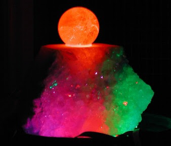
Puzzlemation is an expandable platform of light and animation based on PIC24FJ64GA002. It can be used to create things as diverse as modular animated signs that can be changed by rearranging its tiles, to a uniquely animated puzzle. This project’s display is made of a number of tiles, about 2 inch square with an 8 x 8 array of color LED pixels. Each tile is individually powered and animated, so user can freely pick them up and re-arrange them. To set up a display, the tiles are placed in a special tray. Animations are downloaded into the tray via Ethernet and stored locally on an EEPROM, or loaded via an SD card. The tray broadcasts the animation to each of the tiles, and then synchronizes them.

John Peterson, project designer, said that the display is completely reconfigurable. If the pieces are left in the tray, the animation can be updated continuously over the Ethernet connection. If the tiles are removed from the tray, they’ll display the animation for several hours with their own re-chargeable battery power. Once the animation is synchronized and running on the tiles, user can pick them up and place them anywhere.

Download:
Project Documentation, Source Code and Schematic(zip)
tag :
Display, LED, project, PIC, PIC24FJ64GA002, animation, puzzle

Optical String Tuning Tool, AVR AtMega8

Stimmmopped is AVR ATmega8-based project that will assists you in tuning your string instrument to a given tone. It utilizes the stroboscopic effect to give feedback about the adjustment of your instrument. When the frequency that you chose has tone then the two LEDs on the board blink. Two lines are projected at a fixed position on the string when the string vibrates with the correct frequency. If frequencies don't match, the lines appear to be blinking or moving to the observer's eye. The moving or blinking effect decreases with decreasing difference between the two frequencies.

"The project has two switches to choose the tone and instrument. Switch S1 toggles the current mode of the menu, which is either "choose instrument" or "choose tone". The 7-segment display displays the current selection. In the instrument selection mode, the display is lit up a bit brighter. Switch number two (S2) selects the tone or instrument in the given mode." said Madex (Martin), the designer.

Source Code And Layout

MIDI-Controlled Digital Synthesizer

4bitsynth is 4 bit MIDI-controlled digital synthesizer inspired by the NES. The project is built around Atmel AVR ATMega48 The digital output is put through an R-2R resistor ladder to get the analog waveform. It has three type output : Square wave, Triangle wave and noise.

Project Features Detail :
Triangle

* One volume (uses up/down counter)
* Pitch sweep (up/down, optional looping)
* Standard pitch bend
* Fine pitch bend


Square

* Three duty cycles: 12.5%, 25%, 50%
* Volume decay (optional looping)
* Pitch sweep (up/down, optional looping)
* Standard Pitch bend
* Fine pitch bend

Noise

* Two modes: 93-bit and 32k (think NES)
* Volume decay (optional looping)
* Pitch sweep (up/down, optional looping)
* Standard pitch bend
* Fine pitch bend
more

Saturday, January 15, 2011

AVR Wireless Streaming Radio

AVR Wireless Streaming RadioThe project allow you streaming your radio broadcast wirelessly over internet. The wifi radio built using an Asus WL-520gu wireless router, an old USB audio headset, AVR ATmega8 and other part. If you are interested to build Wireless Streaming Radio, here is the requirement you need to prepare : Wireless connectivity through existing Wifi network; Audio output (preferably 44kHz, 16 bit stereo); Shoutcast/MP3 streaming audio decode; A display to indicate the station and currently playing song; An integrated amplifier and speaker(s); Several built in station presets; and Simple user interface, using standard radio controls (volume, tune, etc).

Gary Dion said that the radio can be controlled over Ethernet and also IR transmitter. The firmware in the project is written in C. You can download the source code here and router shell script. The project inspiration come from Jeff Keyzer.

Mini PSU for Breadboard

Mini PSU for Breadboard
The purpose of the project is to create a 5V mini Power Supply Unit for breadboard. The project can be connected to 8-18 DC power source, or 9V battery. During construction, put the components in as tight as you can, while verifying that you can in fact complete the circuit on the underside of the board without adding any wires. The main component in this project is voltage regulator LM 7805.

To build this you need:

Some electronics skills. Soldering, knowing how to follow a circuit diagram etc..
  1. 1 voltage regulator LM 7805
  2. 1 10uF capacitor
  3. 1 1000uF capacitor (you can use any big electrolyte capacitor here, doesn't have to be exactly 1000uF)
  4. 1 100nF capacitor
  5. 1 LED for power on indication
  6. 1 resistor to take the voltage down from 5V to whatever your LED runs at
  7. 1 screw terminal for the input voltage
  8. 1 switch for input voltage on/off
  9. 1 perfboard, the type with copper eyes, not stripes
  10. 1 2-pin connector to plug the unit into the breadboard
more

Robotic Project

Robotic ProjectThe Lego Mindstorms NXT has been in the market since 2006 and its potential for robotics application is increasing throughout the years. The Lego Mindstorms NXT educational kit consists of several types of sensors and motors, allowing the robot to be programmed to respond autonomously to different types of situations.

The traditional four-directional analog controller allows motion but is restricted by only the four direction keys. The Nintendo Wii remote, which is otherwise known as the ‘Wiimote’, expands on the traditional controller by embedding an accelerometer and Infrared (IR) sensors. The accelerometer allows motion capture of the Wiimote along the XYZ axis as well as detecting the roll, yaw and pitch. Combined with the IR sensors, it allows very accurate motion tracking. With the motion tracking capability on top of the traditional controller capabilities, integrating the Wiimote to a robotics kit will allow the robot to be controlled with more finesse.

For Full Project Download here

Friday, January 14, 2011

Home Automation System with Mobile Communication and Computer Interfacing

Home Automation System with Mobile Communication and Computer Interfacing
Main Features of the projects:
The Home automation project is divided into two parts:
  1. The electrical appliances with computer parallel port interfacing
  2. The remote external on/off of the whole system
The first part contains a interfacing circuits which should be connected with the PC via a parallel port. The computer should need a high definition language such as C, C+, C++, QuickBasic, visual c, c# etc according to user’s choice. The program will define the address of the LPT port for the computer as well as function and status of the devices whether the devices are on or off.
The second part contains a setup which could turn on/off the whole system externally. Here we use cell phone as it is used widely in modern life. The setup contains a mobile set, a decoder and programmable microcontroller. The decoder will decode the signal from mobile to microcontroller and the microcontroller trigger the relay which is connected to the interfacing unit.
Objective/Task of the project:
The main objective of the project is:
  • To generate and develop a circuit that will accept the signals from a computer interface via a port and control the switching of the relays which in turn will control the appliances running on mains power.
  • To analyze and develop the instruction codes utilized by the interface to interact with the device using a high-level programming language.
  • To design a DTMF decoder circuit which decodes the frequency of the button assigned to mobile phone.
  • To connect the decoder with a PIC microcontroller and programming it with necessary condition.
  • Finally Implement and combine the whole system.

For Downloading Whole Project

Solar Tracking System by Microprocessor

This project uses a stepper motor to control the position of solar energy collectors, using Intel 8085 Microp . The software includes the positioning of collectors through stepper motor & data acquisition and processing in Microprocessor.

OPTICAL SENSING AND PROCESSING :

LDR ( Light Dependent Resistance) is used as a sensor for generating an electric signal proportional to intensity of light falling on it. LDR is mounted at the focus of reflector which is directly mounted on solar energy collectors.

STEPPER MOTOR AND ITS DRIVING CIRCUIT:

The stepper motor requires that its stator windings should be energized in a programmed sequence to cause the motor to run in a given direction and with a required speed.

For Downloading Whole Project

Robotic Arm Project


The main objective of this project is to create the virtual representation of a robot’s working environment. This virtual space gives user the ability to test the physical system without ever having to set up the physical environment and also user can practice without having to be on site. Another benefit of using a virtual space is that we can create any representation needed for the user. To control the robot in the real world, as well as the virtual world, we use MATLAB/Simulink to numerically analyze the inverse dynamics of the system. This allows us to specify the robot’s position that we want and then calculate the joint angles that will move the robot to that desired position. The robot will be used to manipulate a set number of objects with known positions within the system, real world or virtual.
Download this project

Wednesday, January 12, 2011

Digital Systems & Microprocessors Project


The project will give you the opportunity to use the RTL technique for the design of a system of modest complexity: a reverse polish calculator with 4 significant decimal digits. The project has various milestones among the specifications to allow you to do a top-down design and to tackle the project at various levels of complexity with plenty of scope for individual creativity. A major aspect of the project will be to explore different approaches of developing the different hardware blocks taking special account of meeting spec and synthesis in hardware.
Download this project